
Product family
Screen installation accessories
SCREEN SUPPORT AND RETENTION
Screen installation accessories connect screen media with deck supports, rails, stringers or retention profiles. Begin with the installed interface, not an assumed accessory name.
Review support channels, rail or stringer protection forms and cappings against visible profiles, dimensions, photographs, drawings or a sample. This does not confirm fit or interchangeability.
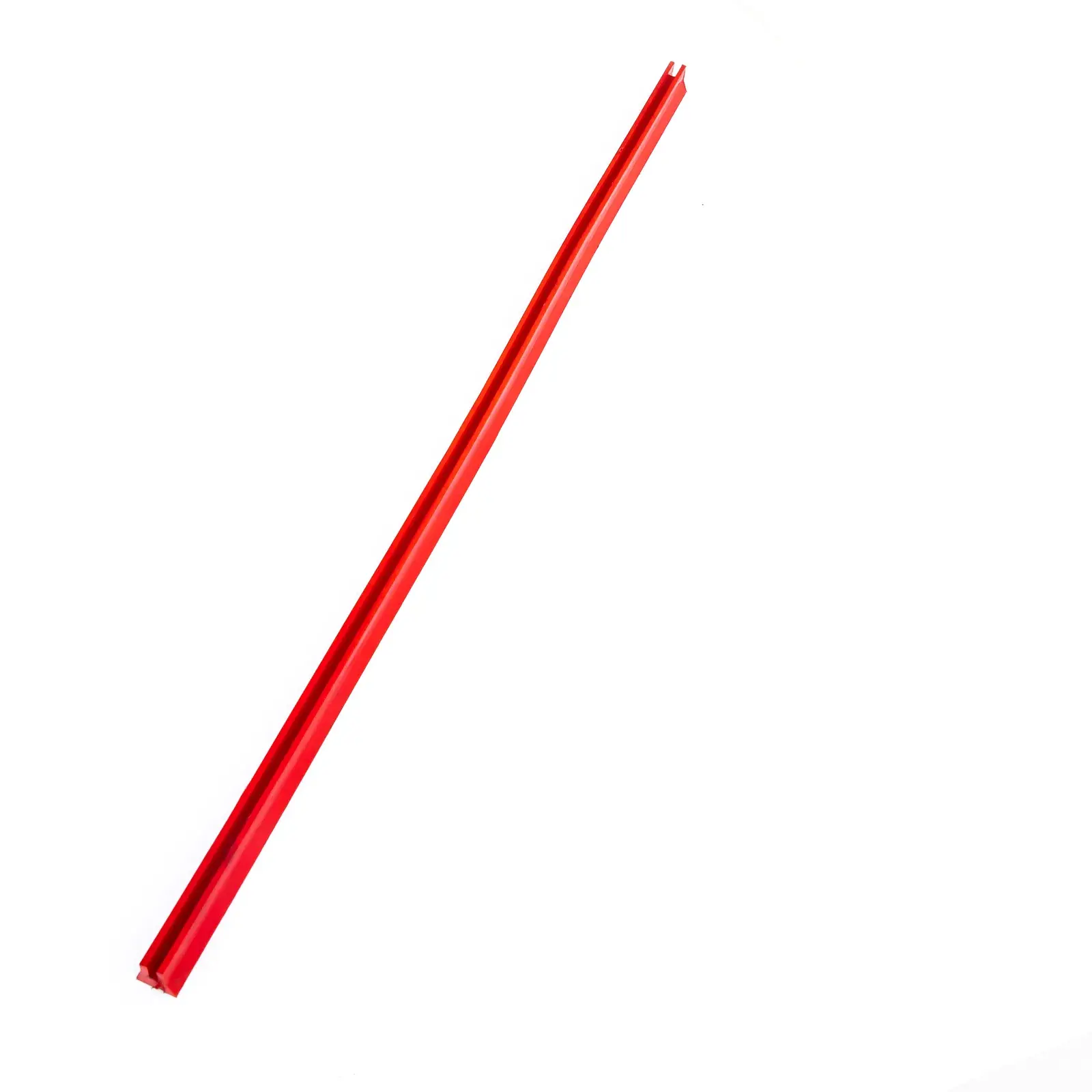
An overall channel view helps establish the accessory form. It does not establish the mating deck profile, installed position or compatibility.
Quick product attributes
Screen installation accessories are supporting components used to retain, support or assist screen-media installations. The current panel, deck arrangement and component profile determine the review.
Product family
Screen installation accessories
Function groups
Fixing and retention, support and protection, spray and washing
Selection basis
Match the existing interface before naming a replacement
Component evidence
Use close photos of the current accessory and installed arrangement
Profile evidence
Record the visible section, mating faces, holes, tabs or channels
Dimensions
Confirm overall and interface-specific dimensions from the current part
Confirmation
Use a drawing or old sample where pictures do not establish the profile
Supply basis
Quotation follows the confirmed interface and available evidence
Function and interface
The three groups below are used to organize an evidence-led replacement review. They do not establish a standard fit for a screen or deck.
Fixing components and retention profiles must match the existing panel and deck interface. Compare the current part, its profile, visible holes or tabs, and the installed arrangement before a replacement is reviewed.
Refer to the single replacement checklist below for the photos, dimensions, drawing or sample details to send.
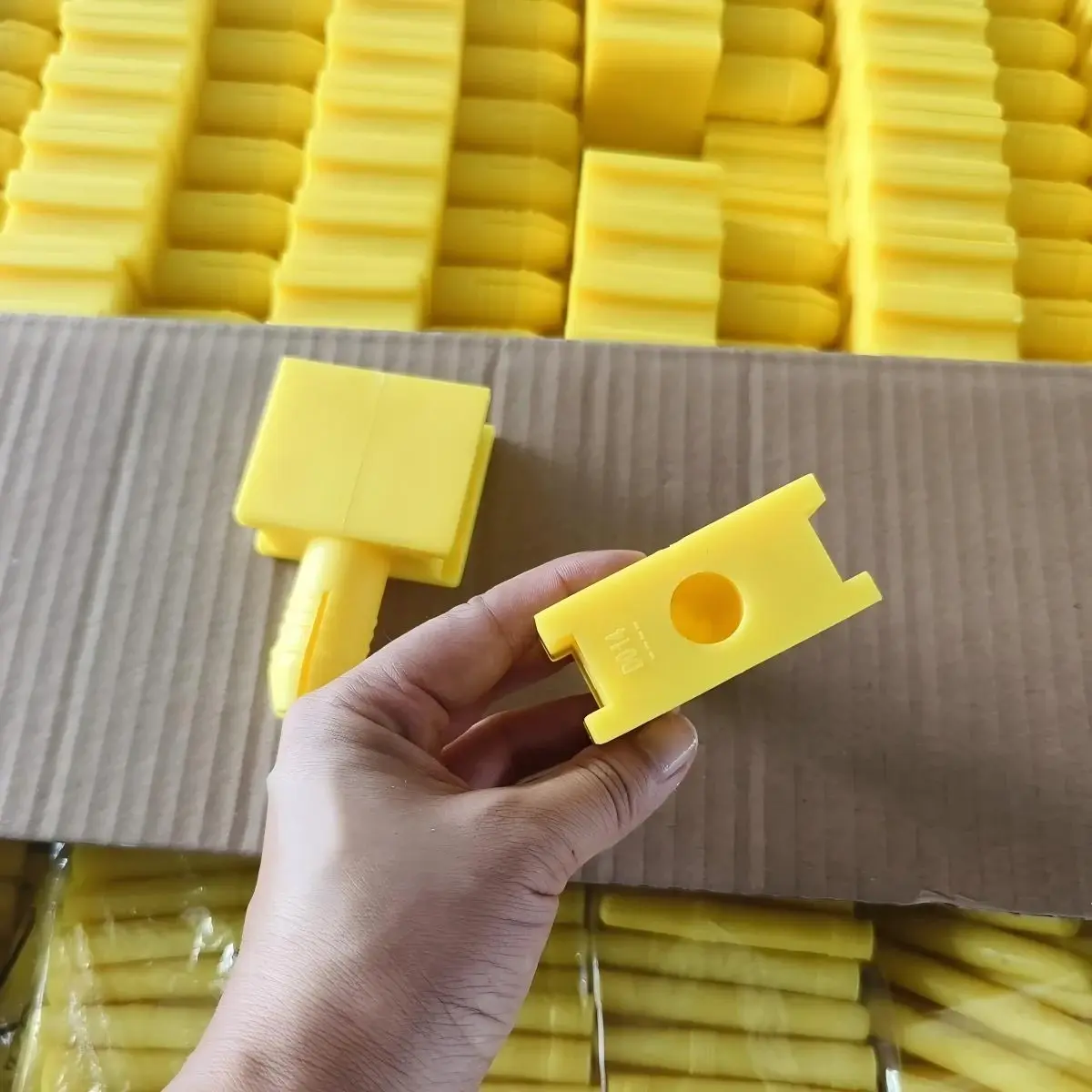
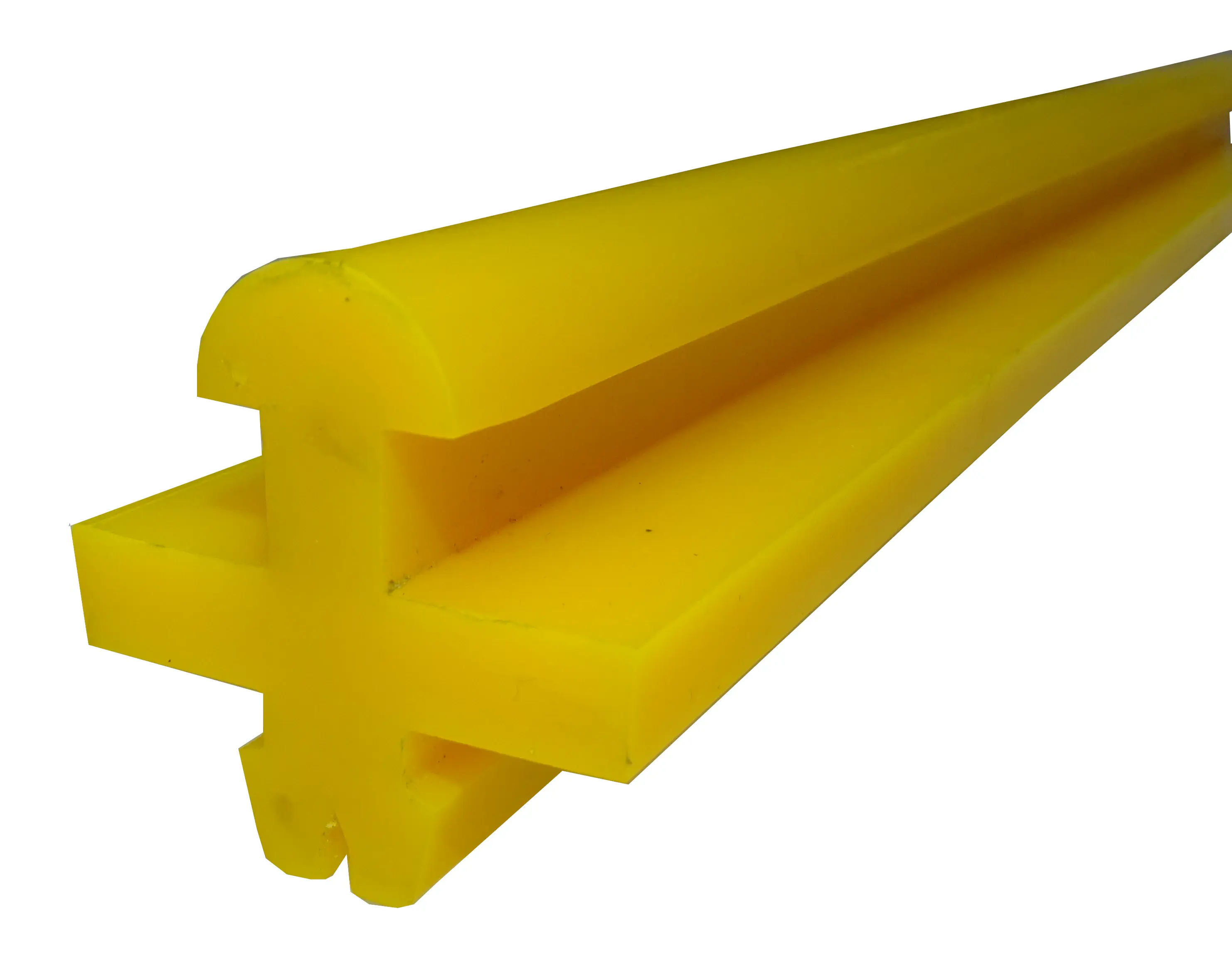
Fixing pin assembly: match the current component and its mating profile before review.
Retention profile: compare the visible profile and installed interface with the existing deck.
Support and capping profiles are selected by matching the existing contact geometry and installed support arrangement. A profile image is a review aid, not proof of a standard support location or fit.
Show the profile cross-section, contact surface, installed location and the current component before quotation.
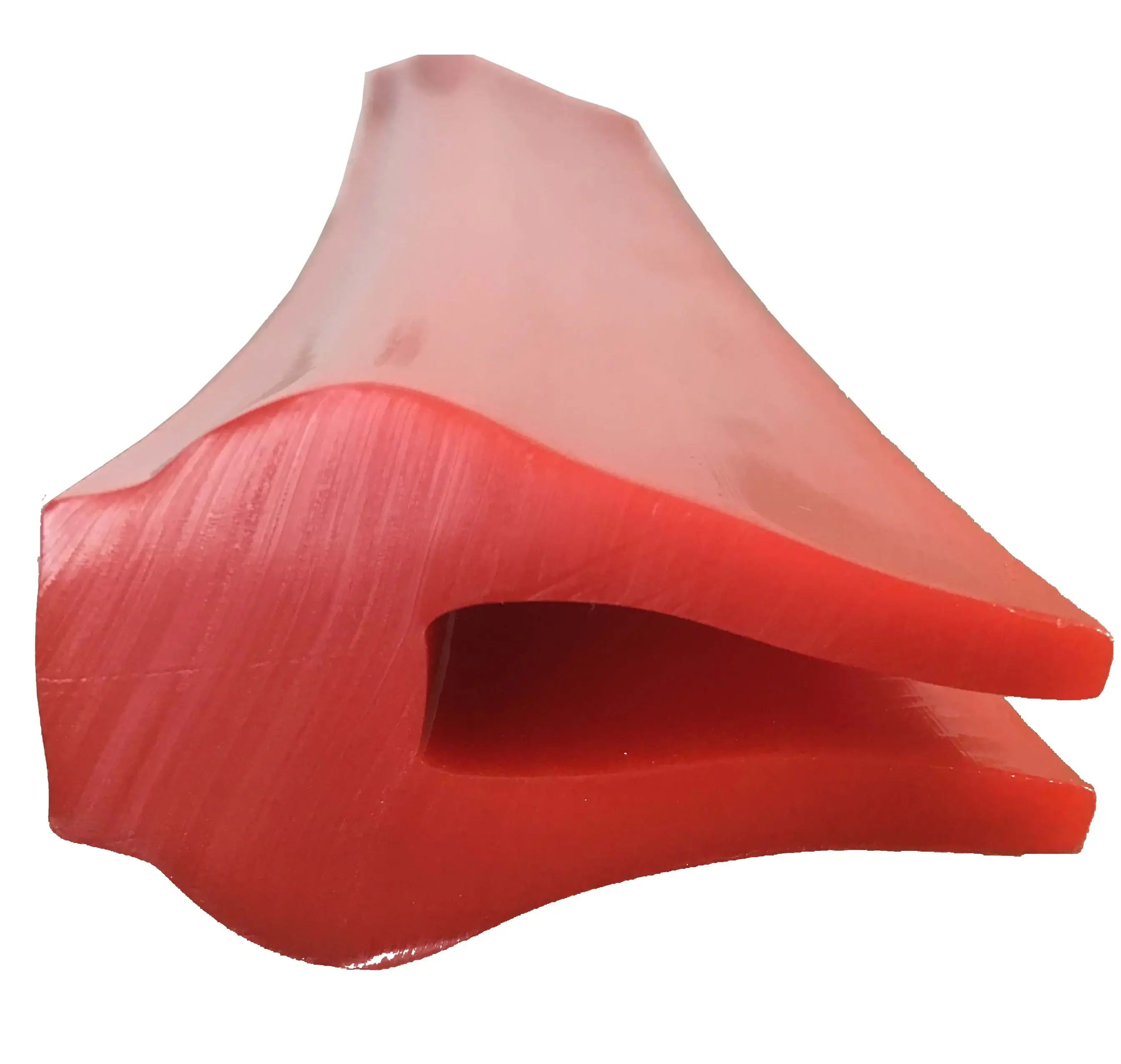
Support capping profile: confirm the existing contact geometry and support arrangement.
Water-distribution accessories are reviewed from the installed screen-deck position and the visible pipe or mounting interface. Confirm the current component and arrangement rather than assuming a hydraulic configuration.
Include the installed position, component photos, overall dimensions, mounting detail and water connection information where known.
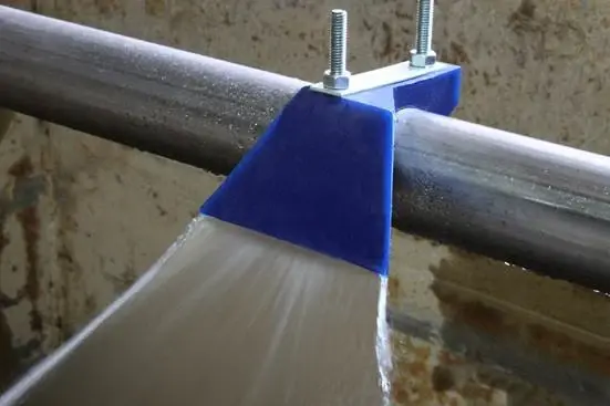
Screen-deck water distribution deflector: review the installed position and pipe interface before quotation.
Replacement checklist
Use one evidence set for the accessory review. A clear unknown is more useful than an assumed interface.
The checklist supports technical and quotation review. It does not confirm a final profile, dimensions, material formulation, mating interface, machine compatibility or installed result.
The review compares the requested accessory function with the current component, interface, photographs, dimensions and available drawing or sample. Where the visible evidence is incomplete, the missing interface detail remains open for confirmation rather than being inferred.
A name, overall length or general product family may help begin the conversation, but it does not replace evidence of the mating surfaces and installed position. The review records what can be compared from the supplied material and identifies what still needs confirmation.
Use a drawing, traced section or old sample when wear, incomplete photographs or an obscured mounting area prevents the existing profile from being identified. This is especially useful when a component name does not show how it mates with the panel or deck.
Related replacement decisions
Use the relevant screen-media page for the panel itself, then bring its deck and interface evidence into the accessory review.
Accessory review
For a quick question, send component photos on WhatsApp. For a formal accessory requirement, request a quote with the available installation and interface evidence.
Identification questions
Prepare observable evidence before asking for a replacement review.
No. A similar name can describe a different profile, mating surface or mounting arrangement. Match the current component, installed interface and available reference evidence before a replacement is reviewed.
Use a drawing or old sample when photographs do not show the original section, interface or mounting detail clearly enough to identify the component.
Send photographs, dimensions or a sample for review. The required accessory is assessed from the existing installation rather than assumed from a broad catalog name.