
POLYURETHANE SCREEN MEDIA
Modular Polyurethane Screen Panels
Modular polyurethane screen panels are replaceable screening modules reviewed against module dimensions, aperture, deck interface, drawings, photographs or an existing sample before quotation.
The installed module, its underside and its neighbouring panels establish the replacement reference. A visually similar panel does not by itself confirm a shared interface.
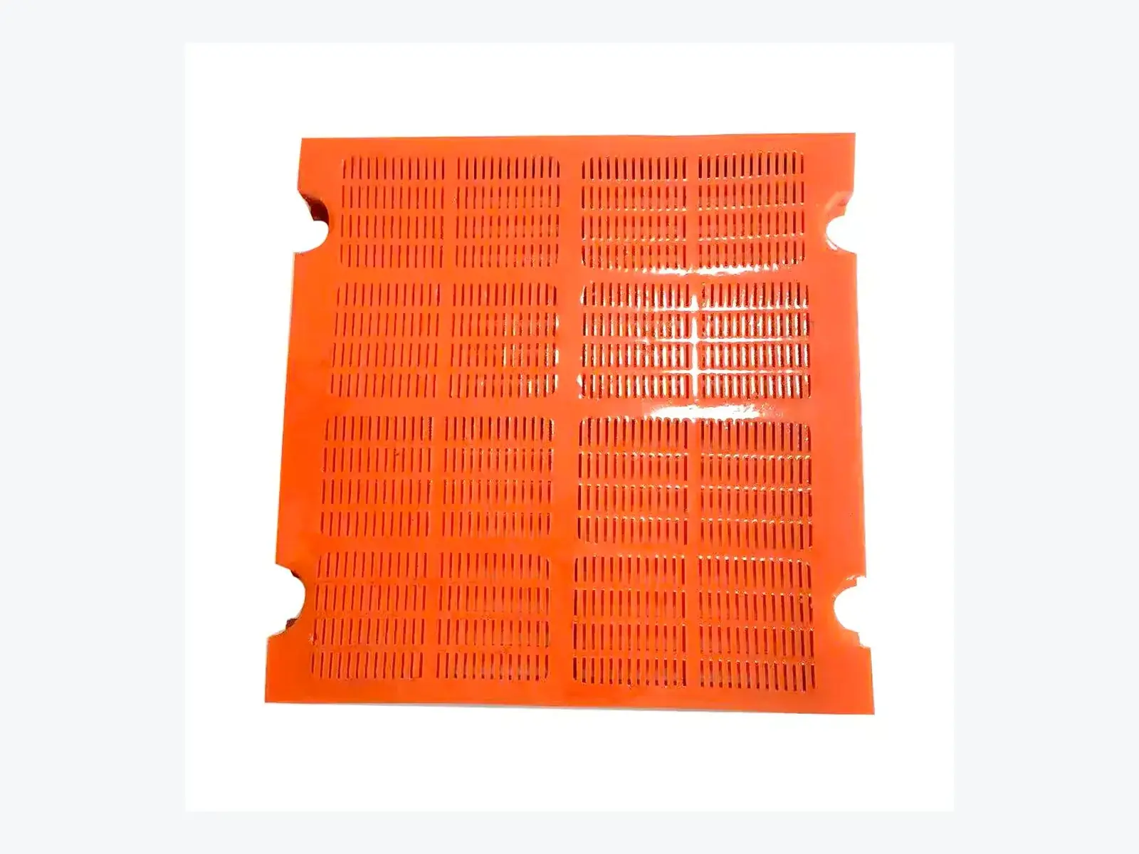
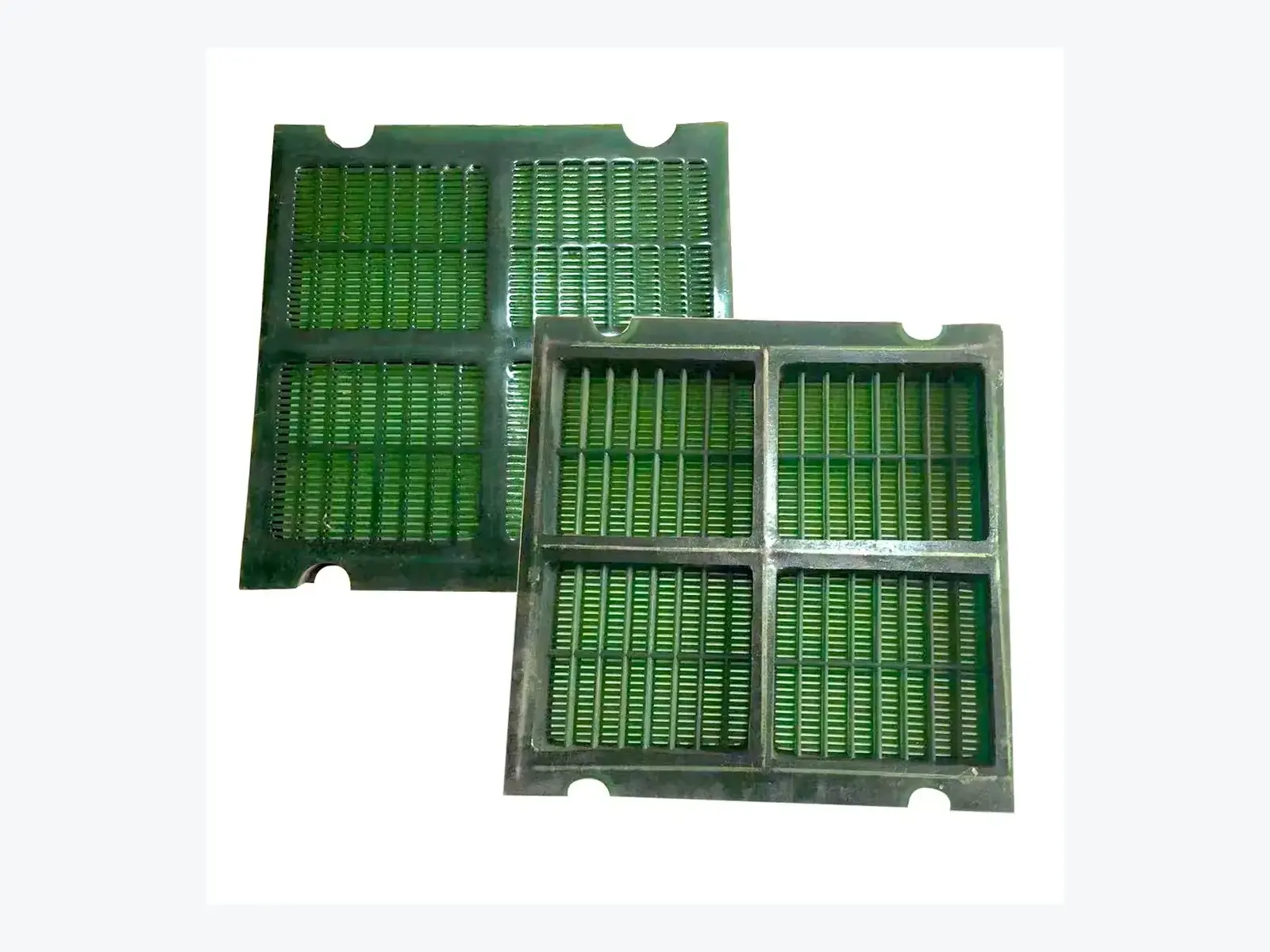
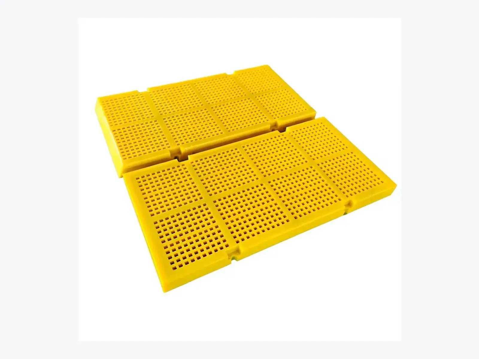
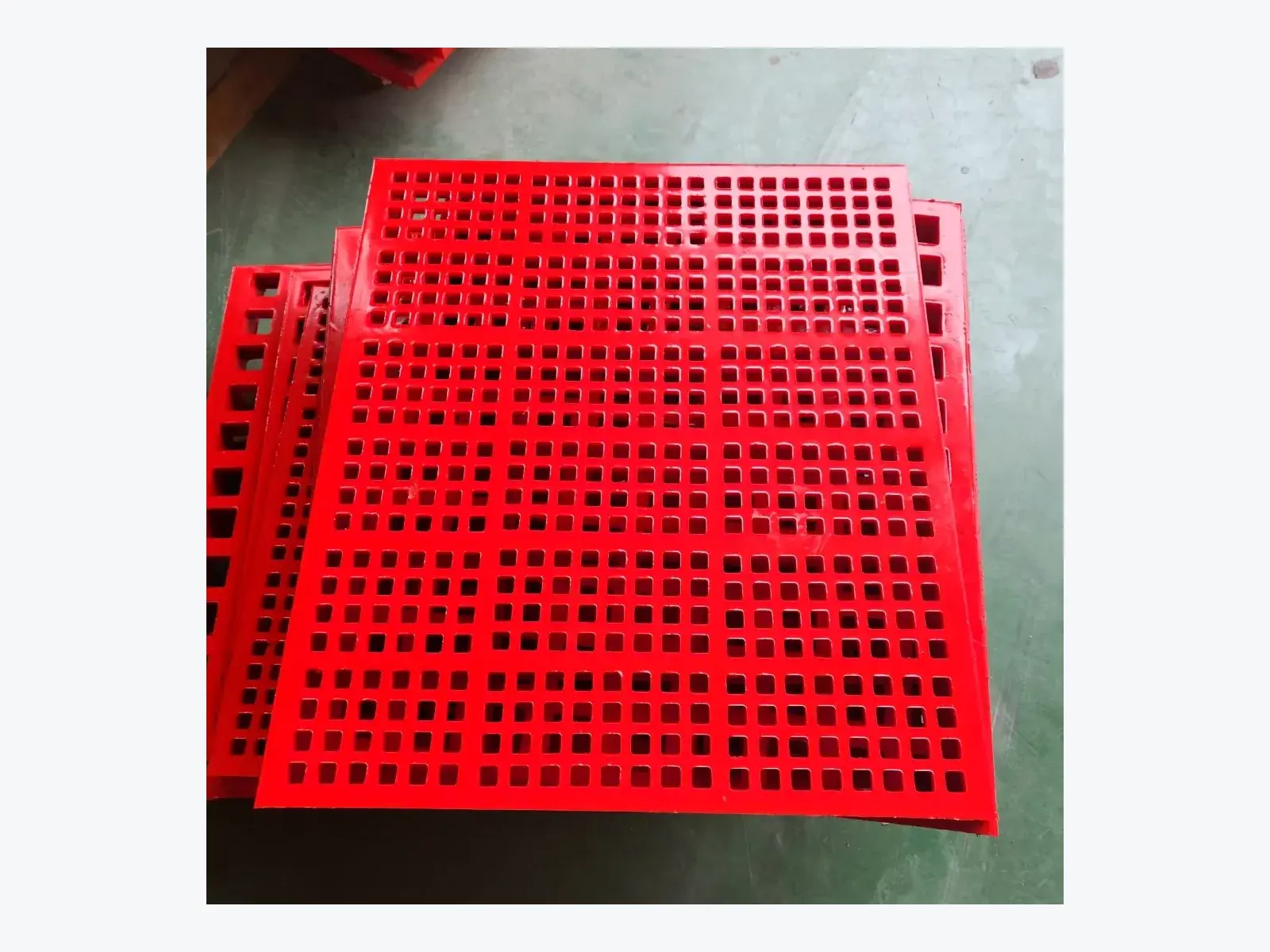
Current approved product views remain the page Hero reference.
Quick product attributes
Match the module before selecting a replacement
Start with the visible module and deck interface, then add process evidence for quotation.
- Product form
- Replaceable modular polyurethane panel
- Selection reference
- Current module, deck and adjacent panels
- Aperture evidence
- Shape, size and direction from the panel
- Interface evidence
- Underside, edges, support and fixing views
- Duty context
- Material condition and required separation
- Deck context
- Wet or dry duty and panel position
- RFQ inputs
- Measurements, photos, quantity and destination
- Confirmation boundary
- Final configuration follows review
Module configuration
Aperture, outline and underside work together
A modular panel is identified by its complete outline, visible aperture form and the surfaces that meet the deck. Record the panel thickness and support geometry from the current reference rather than treating a photographed module as a universal profile.
Aperture evidence
The opening shape, measured details, direction and blank margins should be reviewed with the required separation and material condition. Public images show available configurations, not a fixed family specification.
Module outline and orientation
Record which way the module is installed and where the blank margins meet adjacent panels or deck edges. Mark the deck position in the photo set when more than one panel format is visible. This reduces the risk of applying a correct-looking aperture to the wrong footprint or orientation.
Deck and interface evidence
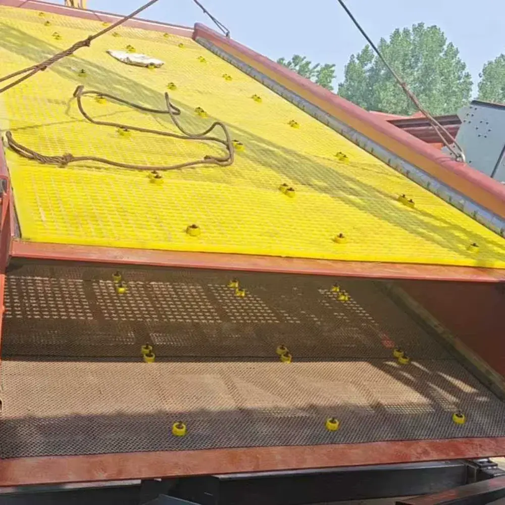
Photograph the full deck before removal, then capture the panel underside, edge, adjacent modules and support or rail arrangement. Where a pin, sleeve, rail or bolt is visible, include it as part of the current configuration rather than assuming it applies to all panels.
A separate retention, rail-protection or capping component can be reviewed with the same evidence through screen installation accessories.
Show the contact surfaces and any gap, rail, support or retaining part that can be safely observed. If a fixing detail is hidden under the panel, note that it is unconfirmed rather than inferring it from the module face. A drawing or removed sample can resolve details that a deck photograph cannot show.
Representative evidence
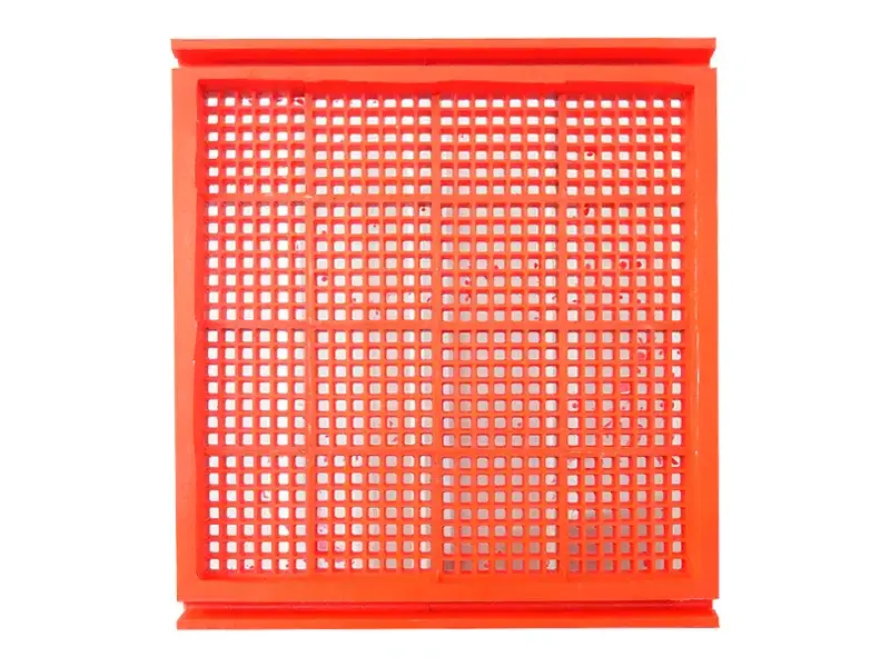
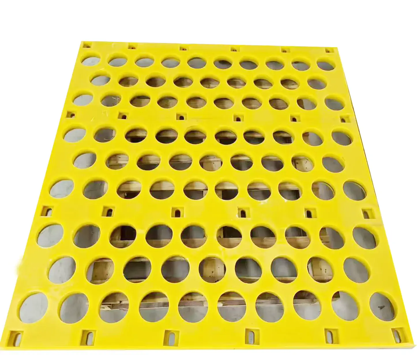
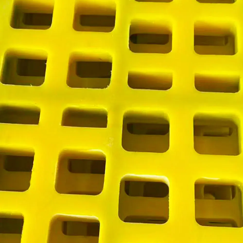
Module, aperture and deck-reference views
These views document photographed configurations and representative deck context. They do not promise universal compatibility.

Replacement checklist
Send one complete modular-panel reference
Keep module geometry, deck interface and operating context in the same RFQ review.
- Overall module length, width and thickness with one stated unit system
- Panel face, underside, side edge and any visible support geometry
- Aperture form, measured opening details, direction and blank margins
- Full deck view, adjacent modules, supports and the installed position
- Visible fixing or retention parts, photographed separately where possible
- Material, wet or dry condition, target separation, quantity and destination
- Drawing, old sample or existing panel reference when available
Operating context and review boundary
Mining and aggregate screening, wet or dry duty, local wear-area replacement and material condition are useful starting inputs. They do not establish a standard module, aperture, deck interface or expected operating result.
State whether the request concerns a single position, a group of adjacent modules or a wider deck area. The quantity and destination complete the quotation context, while the current panel evidence remains the basis for resolving the actual replacement configuration.
For a mixed deck, label each photographed position before the panels are removed and identify any repeated module outline separately. This helps distinguish a common replacement requirement from a local variation. When only a partial sample is available, explain which measured details belong to the sample and which still require a deck photograph or drawing confirmation.
For a single replacement, visually confirm the module orientation against the immediately adjacent panels as well as the broader deck. The nearest interface often supplies the most useful evidence for the requested position.
Questions
Modular panel replacement review
How do I identify a modular panel without a part number?
Start with the full module outline, panel face, underside, edges and the surrounding deck. The adjacent modules and visible support arrangement help distinguish an installed interface from a loose panel photograph.
Which aperture details matter for review?
Record the visible aperture form, measured opening details, direction and blank margins. A square or round photographed opening is a configuration example, not proof that every modular panel uses that pattern.
What fixing methods can be reviewed?
Pin, sleeve, rail or bolt arrangements may be visible on an installed deck. They are examples only: the current panel, support and retention details must be reviewed before a replacement interface is confirmed.
Can ball or vibration-related components be included?
They can be acknowledged when they are present in the current arrangement, but their role and interface remain configuration-specific. The page does not make an anti-blinding or operating-result claim.
What cannot be confirmed from a product image?
A product image cannot confirm hidden construction, final deck fit, formulation, service life, capacity, efficiency or commercial terms. Technical review and quotation confirmation provide those boundaries.